SGLT Linear Servo Motor
Balanced Iron-core coil and magnet track components
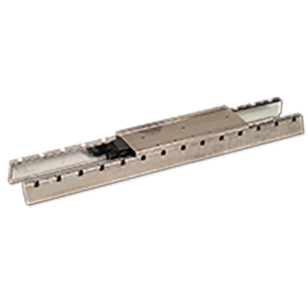
Iron core TW linear motors are composed of moving coils with a laminated iron-core and a pair of stationary magnet tracks that are placed on each side of the moving coils. The moving coil of the TW linear motor is composed of laminated iron core and prewound coil bobbins inserted into the slots located on the laminated iron cores. The entire coil unit is permanently encapsulated in a thermally conductive resin body to give structural rigidity. The magnet track of the TW is made of a row of rare earth magnets accurately placed on one side of the nickelized steel carrier plate. Two of the magnet carrier plates are used as a pair in a fashion similar to that of the coreless type linear motor. Stainless steel magnet covers guard against minor accidental damage to the magnets.
Description
Ratings & Specifications
| Features | |||
|---|---|---|---|
| Duty Rating: | Continuous | Ambient Humidity: | 20 to 80% (non-condensing) |
| Insulation Resistance: | 10MW minimum at 500VDC | Cooling Method: | Self/forced air |
| Motor Type: | Sinusoidally commutated permanent magnet brushless linear motor | Allowable Winding Temperature: | 130ºC (Class B) |
| Ambient Temperature: | 0 to 40ºC | Insulation Dielectric Voltage: | 1500VAC 1 min |
| Specification |
Linear Servomotor Model Number
|
||||||||||
|---|---|---|---|---|---|---|---|---|---|---|---|
|
SGLTW-20A1
|
SGLTW-35A1
|
SGLTW-40A2
|
SGLTW-80A2
|
||||||||
|
170A
|
320A
|
460A
|
170A
|
320A
|
460A
|
400A
|
600A
|
400A
|
600A
|
||
| Continuous Output | W |
325
|
625
|
950
|
550
|
1100
|
1675
|
1675
|
2500
|
2600
|
4000
|
| Continuous Force | N |
130
|
250
|
380
|
220
|
440
|
670
|
670
|
1000
|
1300
|
2000
|
| Continuous Current | ARMS |
2.3
|
4.4
|
6.7
|
3.5
|
7
|
10.7
|
10.8
|
16.1
|
19.3
|
29.7
|
| Peak Force | N |
380
|
760
|
1140
|
660
|
1320
|
2000
|
2000
|
3000
|
4000
|
6000
|
| Peak Current | ARMS |
7.7
|
15.4
|
23.2
|
12.1
|
24.2
|
36.7
|
37.0
|
55.5
|
67.8
|
101.8
|
| Moving Coil Mass | kg |
2.6
|
4.6
|
6.7
|
3.7
|
6.8
|
10.0
|
20.0
|
30.0
|
30.0
|
43.0
|
| Force Constant | N/ARMS |
61.0
|
61.0
|
61.0
|
67.5
|
67.5
|
67.5
|
66.9
|
66.9
|
72.6
|
72.6
|
| BEMF Constant | V/(m/s) |
20.3
|
20.3
|
20.3
|
22.5
|
22.5
|
22.5
|
22.3
|
22.3
|
24.2
|
24.2
|
| Motor Constant | N/ ÖW |
18.7
|
26.5
|
32.3
|
26.7
|
37.5
|
46.4
|
64.1
|
76.6
|
89.7
|
105.4
|
| Electrical Time Constant | ms |
5.9
|
5.9
|
5.9
|
6.9
|
6.8
|
7.0
|
17.8
|
16.5
|
19.3
|
16.6
|
| Mechanical Time Constant | ms |
7.5
|
6.5
|
6.4
|
5.2
|
4.8
|
4.6
|
4.9
|
5.1
|
3.7
|
3.9
|
| Thermal Resistance (with Heatsink) | K/W |
1.01
|
0.49
|
0.38
|
0.76
|
0.44
|
0.32
|
0.34
|
0.23
|
0.28
|
0.19
|
| Thermal Resistance (without Heatsink) | K/W |
1.82
|
1.11
|
0.74
|
1.26
|
0.95
|
0.61
|
0.60
|
0.47
|
0.55
|
0.36
|
| Magnetic Attraction Force | N |
0
|
0
|
0
|
0
|
0
|
0
|
0
|
0
|
0
|
0
|
Note: Values when the linear motor is combined with the SGDH Sigma II amplifier.
1These values are with aluminum heatsink (170A: 254x254x25mm, 320A/460A : 400x500x40mm) mounted to the motor coil.
2These values are with aluminum heatsink (609x762x50mm) mounted to the motor coil.
Flyer
Download PDF
Brochure
Download PDF
Tech Supplement
Download PDF
Product Manual
Download PDF


